
Static mixers are widely used in industrial processes, but improving mixing performance without increasing pressure drop remains a significant design challenge. CEEC developed a GPU-accelerated topology optimisation workflow that uses high-fidelity simulations to generate novel three-dimensional mixer geometries, rather than simply modifying existing designs. In a numerical demonstration, the approach improved the mixing objective by 65% while maintaining the same overall flow resistance, offering a promising basis for developing more efficient mixers for industrial applications.
| Industry | Scientific Domain | Code |
| Chemical & Process Engineering | Topology Optimisation | Neko |
Description of the Challenge
Static mixers are pipe components that mix incoming fluid streams through their internal geometry while keeping pressure drop as low as possible. Used since the 1970s, they serve applications ranging from wastewater treatment and food processing to pharmaceutical and chemical production. Because they have no moving parts, static mixers are reliable, low-maintenance and inexpensive to operate.
However, their performance depends on achieving effective mixing while limiting hydraulic losses. Insufficient mixing can lead to off-specification products, by-product formation in reactive systems, or overdosing of additives to compensate for poor distribution. Excessive pressure drop, on the other hand, increases pumping power and operating costs for as long as the process runs. The design challenge is therefore to balance mixing efficiency with energy consumption.
Optimising static mixers is difficult because their performance depends on the complex, multiscale nature of fluid flow. In laminar flow, typical of viscous liquids such as polymer melts, food products, and pastes, mixing relies on repeatedly splitting, stretching and folding fluid streams until molecular diffusion completes the process. In turbulent flow, typical of water, gases, and low-viscosity chemicals, mixing is driven by turbulent eddies across a range of scales. A geometry that performs well in one flow regime may therefore be a poor choice in another, and industrial mixers must accommodate different fluids, flow conditions and process requirements.
Current designs use geometric features that disturb, split and recombine fluid streams, promoting mixing through mechanisms such as chaotic advection and turbulent diffusion. Industrial users select from established element types, including helical-twist, multilayer crossing-bar, corrugated-plate and tab-type mixers, and choose how many elements their application requires. When mixing is insufficient, the usual remedy is to add more elements, making the mixer longer and increasing its pressure drop, footprint, and material cost.
Computational fluid dynamics (CFD) can analyse the performance of a given geometry, but it does not automatically propose new ones. Designers must still conceive candidate shapes, set up simulations, and evaluate the results. Additionally, these kinds of parametric studies usually only vary a limited number of dimensions within an existing concept. Developing improved or novel mixer geometries therefore requires a way to explore a much broader design space than conventional approaches typically allow.
Why this Matters for Industry
Improving static mixer design could benefit industrial processes through better product quality, lower energy consumption, and more compact equipment. A geometry that achieves the same mixing at a lower pressure drop can reduce pumping energy, while one that improves mixing at the same pressure drop can enhance product consistency without increasing energy demand. The results presented in this Lighthouse Case demonstrate the latter in a laboratory-scale numerical study.
Improved mixing could also support higher reaction yields, more consistent products, and shorter residence times in downstream processing units. In chemical and pharmaceutical manufacturing, effective mixing within a short, well-defined residence time is particularly important for continuous-flow processing. Faster, more uniform mixing could therefore help reduce by-product formation in fast competing reactions and support more compact equipment. These potential improvements would be relevant to the shift from batch to continuous manufacturing in pharmaceuticals and fine chemicals.
Advances in part manufacturing create further opportunities for static mixer improvement. Additive manufacturing can produce complex internal geometries that would be difficult or impractical to make using conventional methods. This is a natural match for topology-optimised designs, which are not restricted to standard mixer elements or a small set of predefined shapes. Combining simulation-driven design with advanced manufacturing could therefore open up new approaches to mixer development.
The industrial opportunity lies in finding geometries that better balance mixing performance, pressure drop, material use, and manufacturing requirements, then validating their value under real operating conditions.
▶ Scientific Background
This Lighthouse Case demonstrates topology optimisation of three-dimensional static mixers in unsteady flow, using time-resolved direct numerical simulation (DNS). Previous topology optimisation studies for mixers have focused primarily on steady, laminar flows, particularly in microfluidic applications, while studies of turbulent flows have relied on steady Reynolds-averaged Navier–Stokes (RANS) models. CEEC’s work advances this field by combining time-dependent flow simulation with large-scale numerical optimisation on GPU-accelerated supercomputers.
Topology optimisation differs from conventional parametric shape optimisation. Rather than adjusting a limited number of dimensions within an existing concept, it determines which regions of a design space should contain solid material or fluid. Internal features can therefore be created, merged, or removed without prescribing a particular mixer layout in advance. CEEC’s work advances the field in three ways:
- Large-scale optimisation: A GPU-parallel implementation of the Method of Moving Asymptotes (MMA) has been demonstrated at very large scale, including separate benchmarks with up to 1.7 billion design variables.
- Time-dependent flow modelling: The workflow uses DNS to resolve unsteady flow without relying on a turbulence model. Adjoint sensitivity analysis is combined with in-situ Proper Orthogonal Decomposition (POD) to compress the flow history required during optimisation.
- Scalable computing: Forward simulations, adjoint simulations and design updates run on the GPUs of LUMI, while CPU resources can be used concurrently for flow-history compression.
The main mixer results were obtained at a Reynolds number of 300, where the flow is unsteady and three-dimensional but not turbulent. Relative to the initial design, the optimisation resulted in 65% mixing improvement while maintaining the same overall flow resistance. These values describe the optimisation objective, rather than a direct percentage improvement in product homogeneity.
Preliminary optimisations at Reynolds numbers of 2000 and 3000 extend the investigation to more energetic, unsteady flow conditions. Further work can establish how the designs perform at higher Reynolds numbers and how their performance compares with commercial mixer geometries under identical conditions.
▶ Technical Details: Exascale Computing Approach
Topology optimisation of static mixers combines high-fidelity, time-dependent flow simulations with numerical optimisation. Each design iteration requires a forward simulation, an adjoint simulation to calculate how the design affects the mixing objective, and an update to the geometry. Because the adjoint simulation needs access to the forward flow state at every time step, managing this data efficiently is a major computational challenge. An optimisation may require hundreds of iterations, making the overall workflow substantially more demanding than a single CFD simulation.
The computational requirements grow rapidly with simulation resolution and duration. For a production-scale configuration considered by the team, approximately one million fifth-order spectral elements would correspond to around 200 million grid points and roughly one billion unknowns per time step. Simulating 12 convective time units with a time step of 10⁻⁴ would require approximately 120,000 time steps. With at least 200 optimisation iterations, the estimated cost could reach around 41,000 node-hours on 16 LUMI-G nodes for a single optimisation.
Higher Reynolds numbers require finer spatial resolution to capture more detailed flow structures, while higher Schmidt numbers increase the resolution needed to represent species transport and mixing. Since each optimisation iteration involves computationally demanding simulations, these requirements quickly add up. Exploring multiple designs or operating conditions adds further work. This is why scalable algorithms and efficient use of GPU-accelerated HPC resources are important for extending topology optimisation to more demanding problems.
To this end, CEEC addressed two important bottlenecks in the workflow.
First, the team developed an in-situ flow-history compression approach based on POD. Instead of relying entirely on checkpointing and recomputing intermediate flow states during the adjoint simulation, the method compresses the flow history as the forward simulation runs. In two complete 100-iteration optimisation cases, this reduced runtime by approximately 29–31%, while keeping final objective values within 1.5% of the checkpointing reference results. Further details are presented in the success story “In-situ Compression of Flow History for Faster Topology Optimisation“.
Second, CEEC developed a GPU-parallel implementation of the Method of Moving Asymptotes (MMA), the algorithm used to update the design at each iteration. Keeping the design update on the GPU reduced CPU–GPU data transfers and helped prevent the optimiser from becoming a bottleneck as the number of design variables increased. In the reported benchmark cases, the design-update step accounted for less than 1% of total runtime. Separate benchmarks demonstrated scalability to very large numbers of design variables, as described in more detail in the success story “A GPU-Parallel MMA Algorithm for Topology Optimisation”.
Together, these developments improve two distinct parts of the workflow: managing the time-dependent data required for adjoint calculations and updating large numbers of design variables efficiently. They make the optimisation process more efficient and scalable on GPU-accelerated European supercomputers, enabling further investigations at higher resolution and under more demanding flow conditions.
Results and New Insights
The optimisation workflow was demonstrated on a square duct in which two fluid streams enter side by side. The streams are represented by a concentration field ranging from 0 to 1. Within a design region, the optimiser distributes solid material to improve downstream mixing while penalising mechanical energy dissipation. Two cases began from the same geometry of three crossing cylinders but used different weightings: one prioritised mixing, while the other assigned ten times more weight to dissipation. Each optimisation was run for 100 iterations using a demonstration-scale computational mesh, although neither design had fully converged by the end of the run.
Balancing Mixing and Energy Losses
The results show how topology optimisation can explore different balances between mixing performance and the energy required to drive flow through the mixer. The optimisation penalises mechanical energy dissipation, which is closely related to the pressure drop across the mixer and therefore to the pumping power required at a given flow rate. In the mixing-driven case, the mixing objective was reduced by 98% relative to the initial design, at the cost of a 2.8-fold increase in total dissipation. In the dissipation-aware case, the mixing objective was reduced by 65% while total dissipation remained essentially unchanged, at approximately 2% below its initial value.
The two cases illustrate different design priorities: maximising mixing even at a higher energy cost, or substantially improving mixing without increasing dissipation. Additional objective weightings could be used to explore more points along this trade-off between mixing and pressure drop.
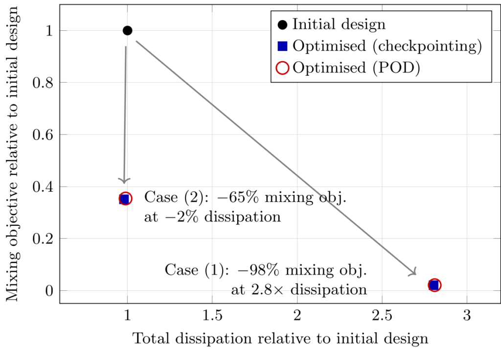
Figure 1: Mixing versus dissipation after 100 optimisation iterations for the two weightings of the objective, normalised by the initial design (three crossing cylinders). Lower is better on both axes. Case (1) prioritises mixing; case (2) penalises dissipation, which at fixed flow rate is directly linked to the pumping power. The two cases represent two points of the mixing/pressure-drop trade-off; additional weightings would trace the full curve. POD and checkpointing give nearly identical results.
New Geometries from a Simple Starting Design
The optimised geometries differ substantially from the initial arrangement of three crossing cylinders. The mixing-driven case produces an intricate three-dimensional structure of plates and struts that repeatedly splits and redirects the incoming streams. The dissipation-aware case produces a sparser arrangement of thin, curved baffles, leaving more open flow passages.
The corresponding concentration fields illustrate the effect of these structures downstream. In the mixing-driven case, the initially separated streams become more uniformly distributed at the outlet. The dissipation-aware design achieves a less pronounced improvement in the mixing objective while keeping total dissipation close to its initial value.
The resulting structures are free-form three-dimensional geometries rather than variations on a predefined catalogue design. Their smallest feature size is controlled by the filter radius used in the design parametrisation, which can be selected with the intended manufacturing process in mind. Metal or polymer additive manufacturing could provide a route to producing such geometries. A next step would be to manufacture prototypes and evaluate their mixing performance and pressure drop against a commercial reference mixer.
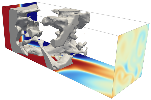
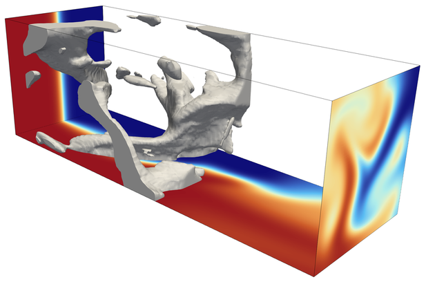
Figure2: Final optimised designs at Reynolds and Péclet numbers of 300 after 100 iterations (checkpointing reference) for the mixing-driven case (1) and the dissipation-aware case (2). The colour on the inlet, bottom and outlet planes shows the concentration field (blue=0, red=1; lighter colours indicate a better mixed state).
Extending the Approach to Higher Reynolds Numbers
Preliminary optimisations at Reynolds and Péclet numbers of 2000 and 3000 show that the workflow can also be applied to more energetic, unsteady flows. Compared with the main demonstration at Re = Pe = 300, the resulting structures are more fragmented and distributed throughout the design region. The flow fields show swirling motion and unsteady vortical structures that transport fluid across the duct and fold the streams into one another.
These observations suggest that the optimised geometries may generate streamwise vortices, a mechanism also used by tab-type static mixers in turbulent-flow applications. Further investigation can establish whether the optimiser is reproducing a comparable mixing mechanism from a generic starting design and quantify the performance of the resulting geometries. Continued optimisation will also help establish how these designs evolve under more demanding flow conditions.
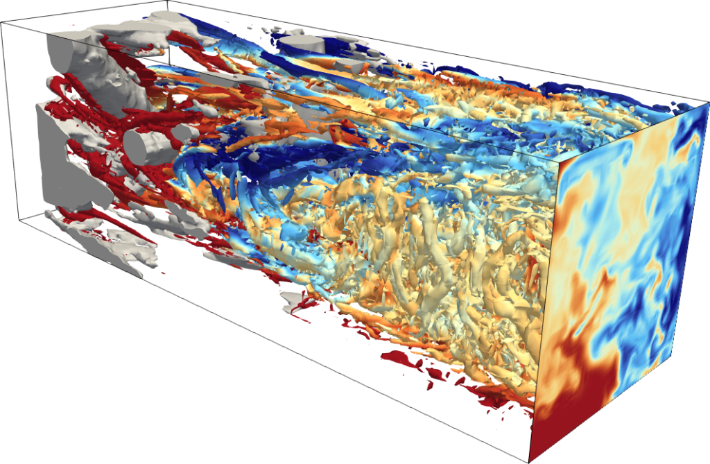
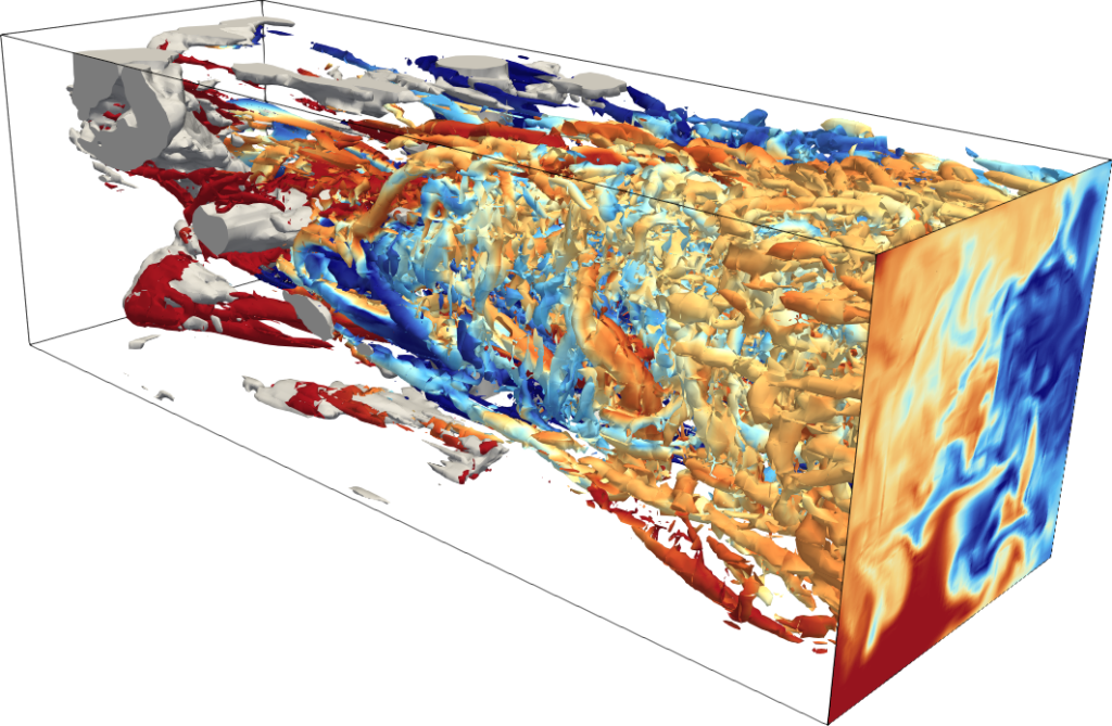
Figure 3: Preliminary optimised designs at Reynolds and Péclet numbers of 3000.
Overall, the results show that topology optimisation can generate substantially different mixer geometries depending on the balance between mixing and dissipation specified in the objective. They provide a basis for further work at higher Reynolds numbers, finer resolution, and a wider range of operating conditions, followed by manufacturing and experimental evaluation.
Industrial Takeaways
The results point to several opportunities for industrial research and development, while further work is needed to establish how the optimised geometries perform in specific applications.
- Better mixing at similar energy demand. In the demonstration case, topology optimisation improved the mixing objective by 65% without increasing total dissipation. At a fixed flow rate, this corresponds to maintaining the same overall energy dissipation while improving the objective used to measure mixing. Future studies could investigate whether similar mixing quality can be achieved at lower pressure drop or in a shorter mixer, with savings quantified against an incumbent design at its actual operating point.
- Transfer across scales and operating conditions. The problem is formulated in dimensionless terms, so an optimised design may be transferable to different pipe diameters if relevant dimensionless numbers, including Reynolds and Péclet numbers, are maintained. Applying the approach at larger diameters or under different flow conditions may require changes to fluid properties or operating conditions, as well as simulations with sufficient resolution.
- Potential CAPEX and OPEX benefits. Lower pressure drop could reduce pumping costs over the lifetime of an installation (operating expenditure, or OPEX). Shorter mixers, fewer elements, or more compact equipment could also reduce material, footprint, and installation costs (capital expenditure, or CAPEX). Additively manufactured mixers may have a higher unit cost than standard elements, so the business case will depend on the application and its energy, product-quality, and space requirements.
- Opportunities beyond static mixers. The optimisation framework is not limited to concentration mixing. For example, the transported scalar can represent temperature, allowing the approach to be investigated for thermal mixing and heat transfer. The GPU optimiser has also been demonstrated on large-scale heat-conduction problems. Future extensions could address reactive flows by incorporating additional transport equations for reacting species, with multiphase flows representing a further direction for development.
- A pathway towards an industrial component. Further development could involve optimising the geometry for an industrial operating point and relevant fluids; converting the resulting material distribution into a surface model for manufacturing; independently verifying mixing quality and pressure drop; producing a prototype, potentially through additive manufacturing; and experimentally comparing its performance with a commercial reference mixer.
The next step is to work with mixer manufacturers, process-industry end users, and additive-manufacturing providers to identify relevant operating conditions and progress towards industrial validation.
▶ Codes and Software Stack
The simulations and optimisation studies in this Lighthouse Case used Neko, a high-order spectral-element framework for large-scale computational fluid dynamics (CFD), and Neko-TOP, a topology optimisation framework built on Neko. Neko solves the incompressible Navier–Stokes equations together with transported scalars such as concentration and temperature. Neko-TOP provides the design parametrisation, objective functions, adjoint solvers, and optimisation algorithms needed to generate new geometries.
High-order spectral-element methods are suited to unsteady mixing problems because they can resolve a wide range of flow scales with relatively low numerical dissipation. They can also represent thin concentration layers, helping distinguish physical mixing from artificial mixing introduced by numerical diffusion. These characteristics are important when evaluating mixing performance and calculating sensitivities for design optimisation.
The work was carried out on the GPU partition of LUMI, the EuroHPC pre-exascale system, using AMD MI250X GPUs. It was supported by the EuroHPC Extreme Scale Access project EHPC-EXT-2025E02-086. Neko has also demonstrated scalability on LUMI-G for other high-fidelity CFD applications, including turbulent Rayleigh–Bénard convection simulations using 37 billion grid points.
The workflow also used a GPU-parallel implementation of the Method of Moving Asymptotes for design updates, Proper Orthogonal Decomposition through PySEMTools, ADIOS2 for data transport, and HDF5 for checkpoint data. Together, these tools support the flow simulations, optimisation, and management of the time-dependent data required for adjoint calculations.
Neko and Neko-TOP are open-source tools intended for use on HPC systems, including GPU-accelerated platforms. The resulting material distribution can be processed into a surface model for further analysis, independent CFD verification, and potential additive manufacturing. The tools and workflow provide a foundation for future studies of optimised mixer geometries and other GPU-based design and optimisation problems, with manufacturing and experimental validation offering a route towards practical application.
Comments
2 responses to “Topology Optimisation of Static Mixers: Designing Better Mixing with High-Performance Computing”
[…] Topology optimisation improves a design by repeatedly adjusting how material is distributed within a given space to achieve a desired objective. Unlike conventional parametric optimisation, which adjusts a limited number of geometric dimensions, topology optimisation can involve millions of design variables describing where fluid or solid material should be placed. […]
[…] Topology optimisation of unsteady fluid flows requires repeated forward and adjoint simulations. The forward simulation calculates how the flow evolves over time, while the adjoint simulation runs backwards through that time history to determine how changes in the design affect the optimisation objective. […]