
The turbulent wake behind a large merchant ship sets the working conditions of its propeller, and with them the fuel burn of the vessel. Today’s industrial CFD tools predict the mean wake reasonably well, but miss the unsteady turbulence that drives propeller loads, vibration, and noise. Using GPU-accelerated, high-order large-eddy simulation with Neko, CEEC produced reference data for the flow around the Japan Bulk Carrier (JBC) that can improve the models used in everyday hull and propulsion design.
| Industry | Scientific Domain | Code |
| Maritime / Shipbuilding | Hydrodynamics / CFD | Neko |
Description of the Challenge
Maritime shipping carries around 90% of world freight, and bulk carriers and tankers make up a large share of the global fleet. These ships are built “full”, meaning that their hulls are almost box-shaped over most of their length and then narrow sharply towards the stern. The Japan Bulk Carrier (JBC), the Capesize reference hull used in this lighthouse case (LHC6), has a length of 280 m and a block coefficient of 0.858, which means it fills almost 86% of the box that encloses its underwater body.
This shape is efficient for cargo, but not particularly hydrodynamic. As the hull narrows at the stern, the boundary layer, the thin region of water that is being slowed-down by striking the hull, thickens rapidly and partly separates. Strong longitudinal vortices form on each side of the hull (the so-called bilge vortices) and carry slow, turbulent water from the hull surface into the region where the propeller operates.
The result is a highly non-uniform and unsteady inflow to the propeller. Each blade passes through fast and slow regions of the wake on every revolution, which causes:
- Fluctuating thrust and torque on the propeller shaft
- Vibration and fatigue in the propulsion system and the stern structure
- Pressure pulses on the hull and radiated underwater noise
- Risk of cavitation, which erodes the blades and adds to the noise
Predicting this stern flow is therefore central to the design of the hull aft body, the propeller, and any Energy Saving Devices (ESDs), such as the wake-equalizing duct fitted to the JBC. It is also one of the hardest problems in ship hydrodynamics: at the Tokyo 2015 Workshop on CFD in Ship Hydrodynamics, where the JBC was the main test case, the stern wake was identified as the region where computations and measurements disagreed most.
Why this Matters for Industry
The shipping sector is under growing pressure to cut fuel consumption and greenhouse-gas emissions, driven by the IMO decarbonisation targets and, in Europe, by the inclusion of shipping in the EU Emissions Trading System. For a large merchant ship, small gains in propulsive efficiency add up to substantial fuel and emission savings over a service life of 20–30 years. Many of these gains are decided in the stern region: the shape of the aft body, the choice of propeller, and the design of Energy Saving Devices all depend on an accurate picture of the wake.
However, in contrast to aerospace, the marine industry has been slower to adopt high-fidelity simulation in design. Industrial practice relies on towing-tank tests and on Reynolds-Averaged Navier–Stokes (RANS) simulations. RANS methods are fast and predict hull resistance and the time-averaged wake with useful accuracy, but they model all turbulence in an averaged sense. For full-form hulls RANS methods have known limitations:
- The level of turbulence in the core of the bilge vortex is underpredicted by a factor of three to ten, as seen consistently across RANS contributions at the Tokyo 2015 workshop
- Results depend strongly on the choice and tuning of the turbulence model, especially where the flow separates
- Unsteady features, such as peak loads on the propeller blades, cannot be predicted by construction
To cover these modelling limitations, designers either rely on additional model tests or apply conservative margins in propeller and stern design. These margins cost efficiency and limit how far new concepts, such as novel ESDs or unconventional aft-body shapes, can be pushed before they are built.
High-fidelity, scale-resolving simulations can close part of this gap. They do not replace RANS in daily design work, but they can show what really happens in the stern flow, and provide the reference data needed to calibrate and improve the faster tools that are, in fact, used in daily design work.
▶ Scientific Background
The JBC was designed by NMRI, Yokohama National University and the Ship Building Research Centre of Japan as an open validation case. The full-scale ship does not exist, but a 7 m model (scale 1:40) was tested extensively in towing tanks at NMRI, SRC and Osaka University, including resistance, self-propulsion, and stereo-PIV measurements of the stern flow. Wind-tunnel measurements of a double-body model were later carried out at the Hamburg University of Technology (TUHH). For CEEC’s work, we simulated the model-scale hull under the 2015 Tokyo workshop conditions (Tokyo 2015, Wageningen 2025): a Reynolds number of 7.46 × 10⁶ based on the hull length, in double-body condition (without free-surface effects), and without propeller and ESD as the baseline.
Analyses after the Tokyo 2015 workshop revealed why this case is so challenging. Hybrid RANS–LES simulations by the group at Centrale Nantes showed that the “averaged bilge vortex” seen in experiments and RANS results is not a single, steady vortex at all. It is the time average of intense, strongly unsteady smaller vortical structures, fed by ring vortices shed from an open separation where the hull narrows at the stern. This explains why RANS models, which assume a steady averaged flow, struggle to converge on refined grids and cannot reproduce the measured turbulence levels in the vortex core. It also shows that the stern flow of a full-form ship is intrinsically unsteady, and must be resolved in time to be understood.
Large-eddy simulation (LES) resolves the large, energy-carrying turbulent structures directly and models only the smallest scales. The main cost driver is the turbulent boundary layer along the hull, which is thin compared with the ship but contains very small, energetic structures near the wall. In general, two strategies exist to simulate the flow around the hull:
- Wall-resolved LES (WRLES) resolves the boundary layer down to the wall. It needs no wall-model and serves as the reference, but its cost grows very steeply with Reynolds number.
- Wall-modelled LES (WMLES) resolves only the outer part of the boundary layer and models the near-wall region with a wall-model that supplies the wall shear stress. Published grid estimates for the JBC indicate around 1.5 × 10⁸ cells for WMLES, compared with about 2 × 10⁹ for WRLES, at the full model-scale Reynolds number.
What has been missing is a combination of both: a well-resolved LES of the complete JBC stern flow at the workshop Reynolds number, averaged long enough for reliable turbulence statistics, that can serve as reference data for wall models, hybrid methods, and RANS. Producing this data, and using the case as a testbed for new methods, was CEEC’s goal for LHC6.
▶ Technical Details: Exascale Computing Approach
A well-resolved LES of a ship hull at model scale is a genuinely exascale-class problem. The flow must be resolved from the thin boundary layer near the bow, through the thickening boundary layer along the hull, into the separated stern region and the wake. Even a small patch of hull surface requires a very large number of grid points, and the simulation must run for many flow-through times to obtain converged statistics of an intrinsically unsteady wake.
LHC6 uses Neko, the high-order spectral element code developed at KTH in collaboration with FAU, which runs natively on GPUs and other accelerators. Within CEEC, LES and WMLES functionalities were added to Neko, including the most common sub-grid scale models and wall-models. On top of the classical wall-models, a reinforcement-learning based wall-model approach was also combined with Neko and will be tested within WMLES runs for LHC6. Additional features were also implemented and will be applied within the LHC6 simulations and post-processing such as:
- uncertainty quantification (UQ)
- a fault tolerance framework
- gradient jump penalization (GJP)
- operator-integration-factor splitting (OIFS) scheme
- mixed-precision and compression strategies to reduce storage and energy consumption
CEEC’s final simulations for this lighthouse case are ongoing and organized as follows:
- Reference simulation: a well-resolved LES of the double-body JBC at Re = 7.46 × 10⁶, used to analyse the flow physics and produce reference data.
- Method testbed: simulations using the methodological developments of CEEC, in particular wall-models and reinforcement-leaning enriched wall-models, compared against the reference data.
The simulations are being run on the pre-exascale EuroHPC supercomputer LUMI (LUMI-G), using up to 480 GPUs.
Results and New Insights
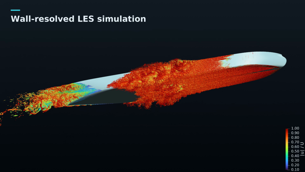
Simulations are ongoing so results will be added to this article at a later date. IN the meantime, the below figure shows WRLES of the flow around the ship hull, at a normalized velocity, within the initial phase of the simulation.
Industrial Takeaways
CEEC’s modelling framework will offer several practical benefits for shipbuilders, propeller designers, and classification societies:
- Reference data for the stern flow of a full-form hull, which can be used to calibrate and validate RANS turbulence models, hybrid RANS–LES methods, and wall models used in industrial CFD
- Improved understanding of the unsteady propeller inflow, relevant for predicting blade loads, vibration, pressure pulses, and cavitation risk
- A physics-based basis for evaluating aft-body shapes and Energy Saving Devices, where time-averaged methods give an incomplete picture
Ultimately, more reliable stern-flow prediction supports more efficient hull and propulsion designs, and with them lower fuel consumption and emissions over the lifetime of the ship. High-fidelity simulation will not replace towing-tank tests, which remain essential for verification, but it can reduce the number of design iterations needed and allow new concepts to be assessed earlier and validated faster. In the longer term, the same approach, combined with wall modelling and further growth in computing power, opens a path towards scale-resolving simulations at full-scale Reynolds numbers, where no experimental data exist.
▶ Codes and Software Stack
Neko
Neko is a portable, open-source framework for high-order spectral element simulations of incompressible flows, developed at KTH in collaboration with FAU. Written in modern Fortran with an object-oriented design, it hides hardware-specific kernels behind a common interface, so the same simulation runs on CPUs, GPUs, and other accelerators without changes from the user.
Its key characteristics include:
- High-order spectral element discretisation, which gives low numerical dissipation and accurately preserves small-scale turbulent structures, essential for LES and DNS of wall-bounded turbulence
- Fast, matrix-free tensor-product operator evaluation for high efficiency on a single GPU or CPU core
- Backend-agnostic design, with support for GPU architectures from several vendors
- High scalability on the largest European HPC systems
The open-source nature of the code facilitates further development and potential adoption by both academic and industrial users.